

In nanoCAD Mechanica, there is a library of standard parts, these standard parts are created by a number of elements, which are parametric objects and are joined by certain constraints. These constraints which relate to the elements are defined by certain rules.
A parametric object is an element with a geometry controlled via parameters.
The MechWizard module in nanoCAD Mechanica helps you to create objects, whose parameters are associated with certain dependencies not only within the object but also with the parameters of other library objects. This allows you to generate different versions or types of the same object using parameters, as well as manage multi-component assemblies, creating different variations of a single object or product as a whole.
This article with examples and figures describes some features of the parameterization module in nanoCAD Mechanica and can serve as a short tutorial on creating parametric elements.
Preparing the object’s geometry. Creating a library element.
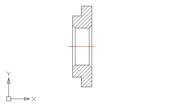
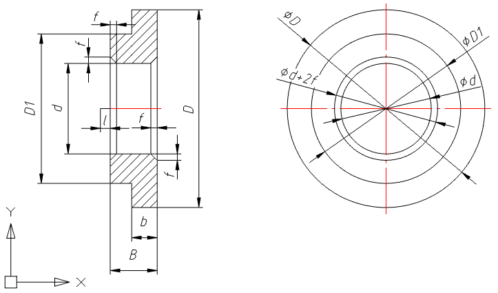
To create a parametric part, using standard nanoCAD tools, we will draw a simple geometric object consisting of primitives. The object can also be imported in *.dwg format from another software (Figure 1).
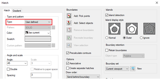
While drawing the hatch, select the Type-User defined. You will need this later for parametric geometry recognition while creating a library object (Figure 2).
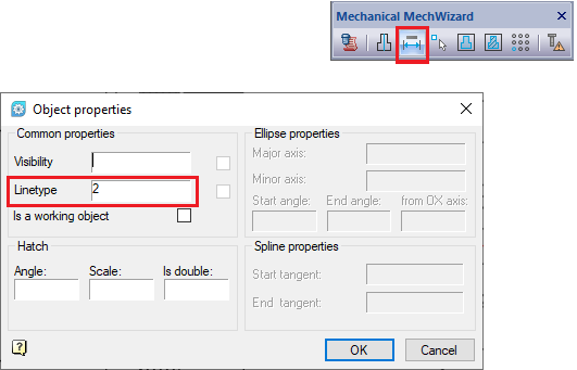
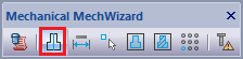
To display the hatching correctly, you must set the line type for the hatch line (Line type: 2). To set the line type, select from the menu tree Mechanica – Standard parts – MechWizard – Set parameter. You can also run this command with the corresponding button on the MechWizard toolbar (Figure 3).
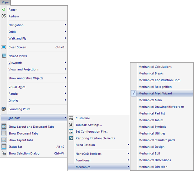
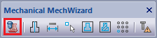
For the frequent use of the Mechanica and MechWizard tools and for the convenience of working with the ScriptMastertool, we recommend using the MechWizard toolbar. To display the toolbar, select the View menu and go to Toolbars -Mechanica – Mechanical MechWizard (Figure 4).
Let’s draw the second view and give the dimensions. It is important that all dimensions that represent the same geometric elements must have the same values on different views. (Figure 5).
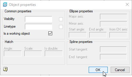
The “l” parameter in the first view is required to create an insertion point. To define it, create an additional segment for setting the segment parameter. To do this, call the menu command Mechanica – Standard parts – MechWizard – Set parameter (or click the corresponding button on the MechWizard toolbar), select the segment and press Enter. In the Object Properties window that opens, enable the Is a working Object option and click OK (Figure 6).
Both views are now ready, now first we will create a symmetric axis for the views, to do this select the Symmetry axis tool in the MechWizard toolbar and select the center lines for both views.
Now that the element geometry has been created and the defining dimensions have been given. Let’s create an object in the library of parts. To do this, call the SriptMaster via the menu Mechanica – Standard parts – MechWizard – ScriptMasteror by clicking the ScriptMasterbutton on the Mechanical MechWizard toolbar.
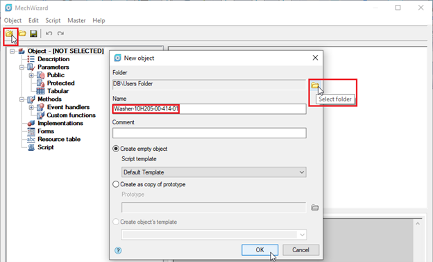
In the MechWizard window that opens, select New Object from the menu or click New Object. In the New Object window, select the library folder where the object will be saved (in this case, User Folders), fill in the Name field, and click OK (Figure 7).
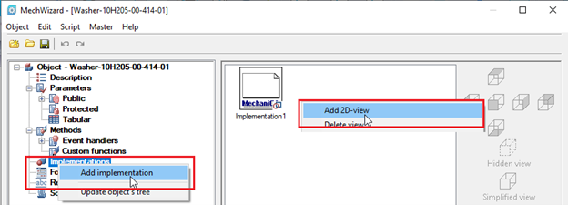
The object has been created, now we will add the geometry. In the MechWizard, right-click on the Implementation branch and select Add implementation from the context menu. By clicking the RMB in the Wizard‘s workspace, we’ll create another view (Figure 8).
Let’s label the first view as the Front View (to do this, select it and click on the corresponding View display button), and let’s label the second view as the Side View (Figure 9).
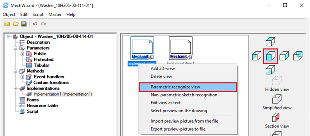
Now we will assign the corresponding geometry to the views created in the Object Wizard. To do this, click the Right Mouse Button on the view and select Parametric recognize view from the context menu. The system will switch to Model mode. Select the object, then select Enter in the context menu or press Enter on the keyboard (Figure 10).
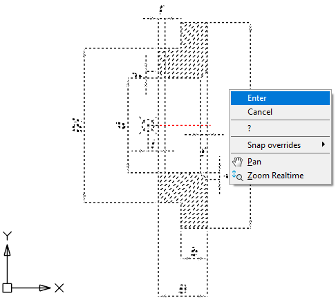
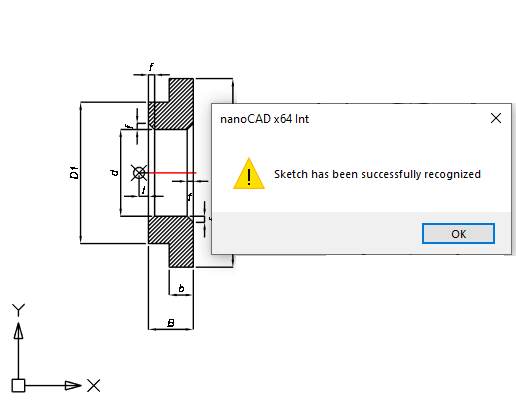
To complete the operation, select the insertion point (the left edge of the “l” segment). If recognition is successful, a corresponding message will appear (Figure 11).
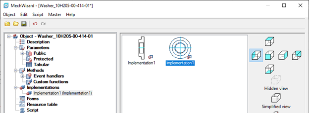
We perform similar operations for the side view. Select the center of the object’s coordinate axes as the insertion point (Figure 12).
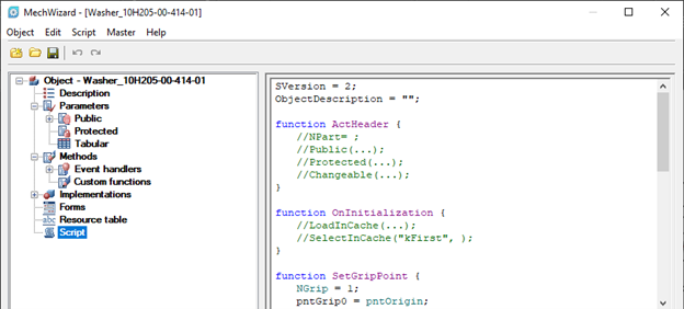
In the object tree, go to the Script branch. The program code for the object description opens in the workspace, where the main functions are displayed by default (Figure 13).
So, it has been illustrated above how in nanoCAD Mechanica, using the ScriptMaster, we can create a library object and define geometry to it. In the next part, we will show you how to parameterize this object using the ScriptMaster, as well as using a referent object.
Leave a Reply